Legacy radio going FASST (2.4ghz), Part 2
(Please read part 1 first.)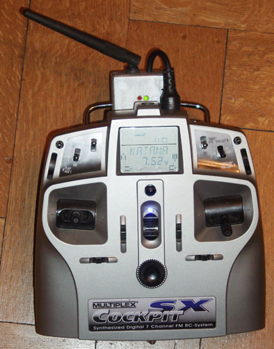
A microcontroller based interface
I have made a second adapter type for my son's Multiplex Cockpit SX. The Cockpit SX, like other entry level models, has some limitations that do require more effort in the interfacing circuit. One of the limitations is that the throttle control is hard-wired to channel 4, while the T6EXP has it on channel 3. You need to swap the channels in order to utilize the failsafe function for the throttle channel. The other one is that the SX transmits only seven channels, while the R606, R607, and R617 FASST receivers expect the failsafe position to be transmitted on channel 8. Of course you want to have the motor stopped in case of a transmission shut-down, so you need to transmit a -100% signal on channel 8. That is why I choose an ATtiny25 microcontroller to do the job.
There is also a software version available that does not swap channels. I am using that version now for my Evo. See below.
I am not recommending this modification to anybody. I am only reporting what I did and how. Because of the high risk a transmitter shut down could cause, the adapter circuit should be built and used only by people who have sufficient skills in building electronic devices and in microcontroller programming. If you wish to do so you do it at your own risk.
For this adapter I decided to transplant the piggy packed tx module from the larger circuit board, which carries mostly unused parts anyway, to the new interface board. It took some time to carefully unsolder the three pin rows that carry the module from the larger board, but it payed off. After having done so, I was able to make the whole package small enough to fit into a compact box. I have placed three single-in-line connectors (two with 3 pins, one with 5 pins) on the interface board, so that the three pin rows of the tx module can easily be inserted.
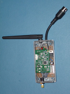
The wiring of the pins is not hard to discover if you look at the solder side of the board that originally carries the tx module. Signal in, Ground and 5V from the stabilizer are connected to three pins of the 5-pin row. Two leads of one of the 3-pin rows go to the LEDs (active low, no resistors required, connect the anodes to 5V). The other 3-pin row is for the 'France' switch (connect one pin to ground, leave it open for 'General' setting).
The interface circuit itself is even simpler than the one with the 555 timer chip, since the the timing is now controlled by a small piece of software in the ATtiny. It is possible to run the ATtiny25 in the default configuration using the internal 8 MHz RC oscillator. Nevertheless, for safety reasons, I strongly recommend applying a quartz stabilized clock that is less sensitive to temperature influence. I am using an integrated quartz oscillator connected to pin 2 of the ATtiny25.
In order to choose the external clock option I had to set a flash fuse bit in the microcontroller. Using an 'AVR910' compatible programmer and 'avrdude' as the programming software, the following command line worked for me on the Mac:
./avrdude -p attiny25 -P /dev/cu.SLAB_USBtoUART -c AVR910 -U lfuse:w:0x60:m
In a different environment, of course, you must set the parameters -p (device), -P (port), and -c (programmer) accordingly.
The source code was written for the GCC compiler using XCode on the Mac. The software swaps channels 3 and 4, so that the regular SX motor channel 4 is transmitted in the place of channel 3, while the SX rudder channel 3 goes as channel 4. It also adds the motor off signal on channel 8, so that the failsafe feature works as expected.
Another version of the ATtiny code does not swap channels. In case the PPM signal carries less than seven channels it fills up the missing channels providing neutral servo positions. It also adds the motor off signal on channel 8 to make the failsafe function work in case channel 8 is unused. Alternatively you may transmit the failsafe position using channel 8 on the radio.